'HORUS'
a balloon satellite
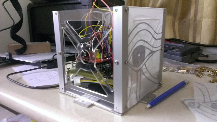

The aim of the project is to design an arduino-powered satellite that is capable of performing aerial surveillance and weather monitoring. The system consists of two entities - a balloon satellite suspended form a helium balloon and a ground control station which allows for wireless operation of the satellite after launch. Weather monitoring is provided by sensors housed in the satellite, with onboard recording of data as well as data transmission to the control station for real-time monitoring. Surveillance is achieved through a camera which transmits video to the control station monitored from a TV screen. The camera has pan-tilt-zoom controls and an automatic active stabilization mechanism. The processor used for both the satellite and the control station is the Arduino Mega 2560, powered by a 1000mAh 3-cell Lithium Polymer battery. An acrylic, aluminium and paper chassis holds all the components together.
The group involves a mechanical team and an electrical team. Since I was part of the electrical team, this will focus more on the electronic systems.
Design Requirements
| Requirement |
Maximum |
| Mass | 1100 grams |
| Dimensions (LxBxH) | 15 x 15 x 15 or L+B+H less than 45cm |
| Operating Height | up to 60m |
| Orientation and Heading | able to determine |
| Sensors | temperature, pressure, altitude, magnetic field |
| Camera Control | can be manipulated from ground |
| Communication Link | established between satellite and ground |
Satellite
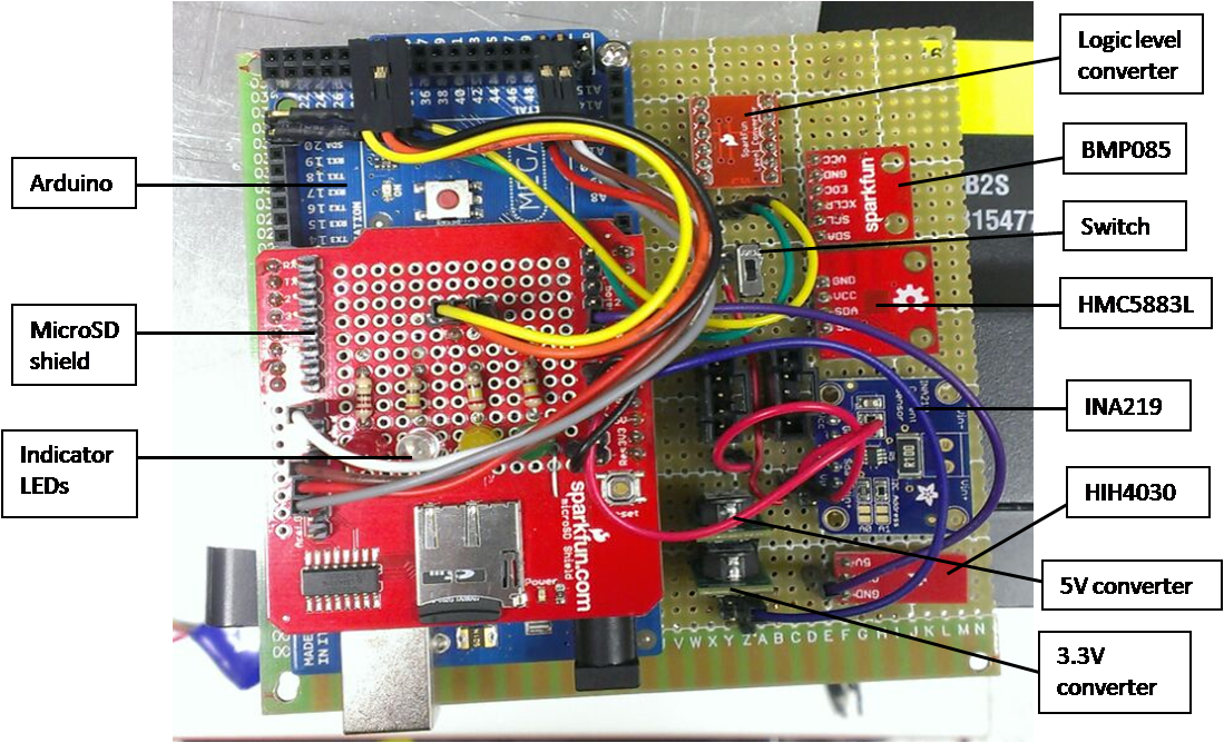
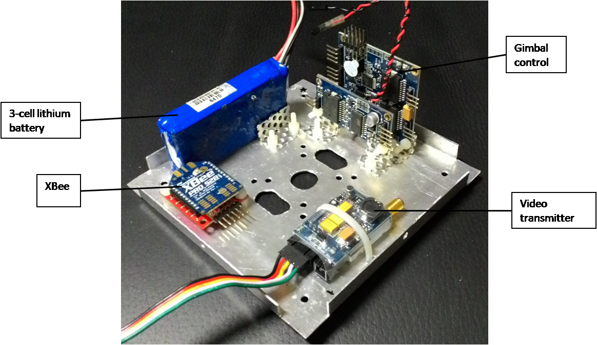
1. top plate; 2. base plate
| Component |
Model number |
Operating Voltage (V) |
| Barometer | BMP085 | 3.3 |
| 3-axis digital compass | HMC5883L | 3.3 |
| Humidity sensor | HIH4030 | 5 |
| Voltage and current sensor | INA219 | 5 |
| XBee | - | 3.3 |
| microSD shield | - | 5 |
| Camera | RT870E | 11.1 |
| Video transmitter | - | 11.1 |
| 3 Brushless DC motors | - | 11.1 |
| Gimbal controller | - | 11.1 |
| LEDs | - | 5 |
| Fan | - | 11.1 |
| 5V voltage converter | - | - |
| 3.3V voltage converter | - | - |
| Logic level converter | - | - |
The operation of the system consists of 2 main parts - the control of the sensors and the control of the camera. The satellite first checks if any commands are given to control the camera. If a command is given, the camera is controlled accordingly before proceeding to take measurements.
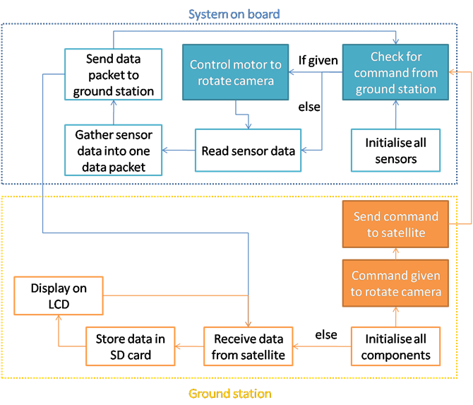
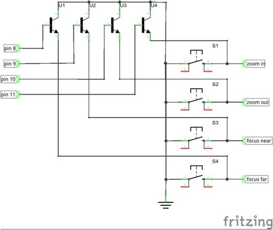
1. System control flow; 2. Schematics for camera control (zoom and focus)
All sensors, except HIH4030, installed on the satellite use an I2C interface. Commands from the Wire.h library is used to extract the readings from the sensors. Libraries for INA219, BMP085 and HMC3558L were also available to ease the use of the sensors and shorten the code. In reading HIH4030, an analog input pin was used to capture the humidity measurements. There are 4 camera commands - zoom, focus, pan and tilt. The intention of the user will be indicated as a digital HIGH in the respective pin and sent to the satellite through the XBee communication module. In controlling the zoom and focus, 4 transistors were used as digital switches to operate the zoom in, zoom out, focus near and focus far push buttons on the controller attached to the camera. When a command is given to zoom or focus the camera, a digital HIGH will be sent to the base of the transistor which then allows a connection between the collector (which is connected to ground) and the emitter (which is connected to the push button of the controller). A digital LOW will be sent to the base of the 3 other transistors to disable the connection between the collector and the emitter. A delay of 100ns was also necessary to allow time for the camera to respond. In controlling the pan and tilt mechanism, an increment or decrement of 100us will be written to the respective motors.
Ground Control Station
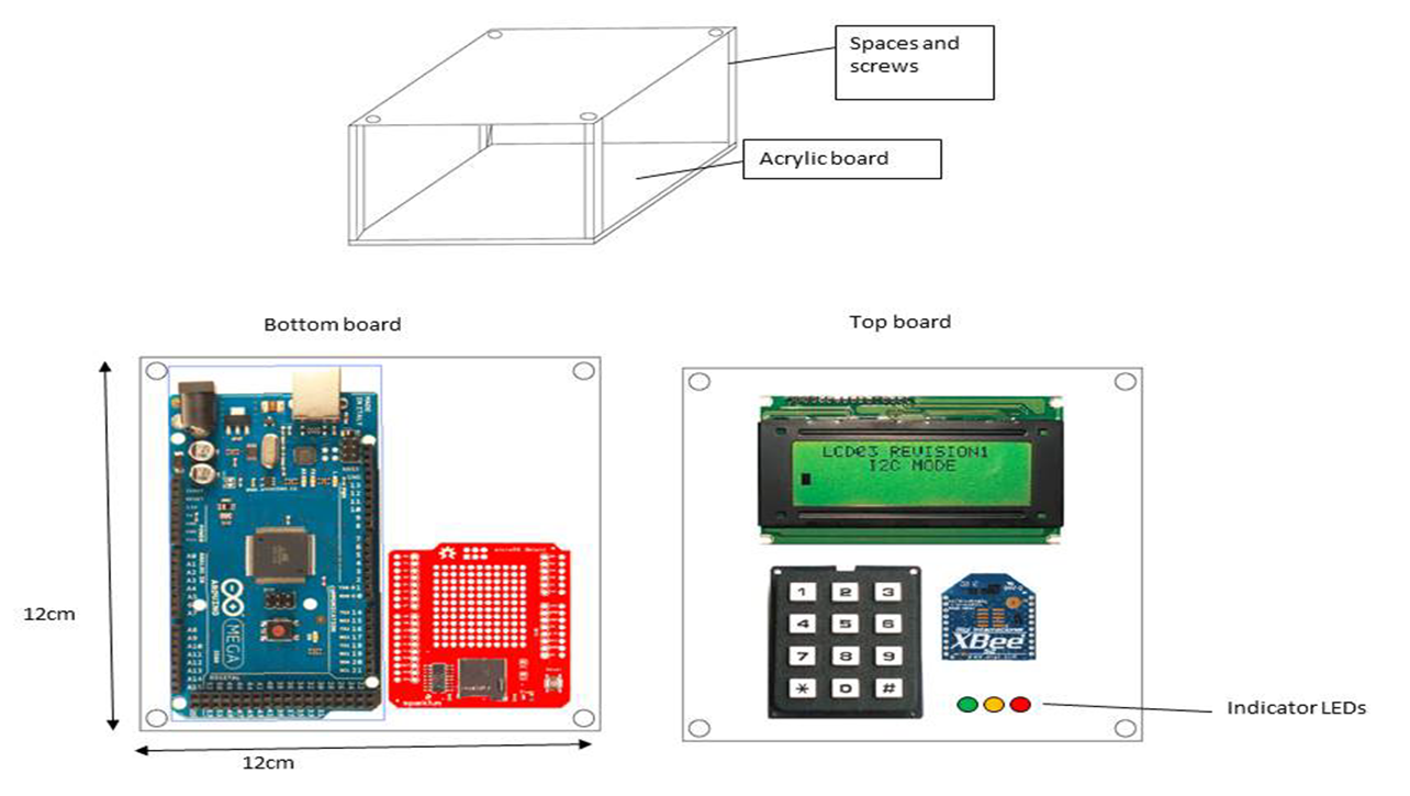
The control station consists of an Arduino Mega 2560 and MicroSD shield for information processing, a 20x4 LCD screen and indicator LEDs for information display, a keypad to provide user input, and an XBee communication module to communicate with the aerial unit. THe RC305 video receiver connects directly to a TV display. The UI of the ground station operates by modes, with each mode mapping a different set of inputs to outputs. To create a more compact station, the components are installed on 2 acrylic boards. The components that do not play an active role in controlling the satellite are kept at the bottom tray.
The ground control station has 3 modes - mode 1 displays the sensor readings, mode 2 allows for camera control, mode 3 allows for system monitoring (i.e. current drawn by the system, power consumed, battery voltage level, data transfer rate).
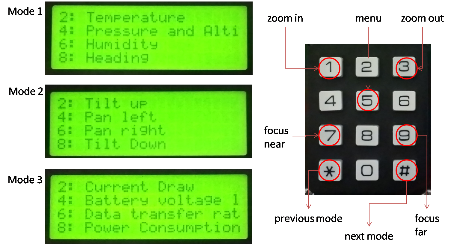
| Keys |
Mode 1 (sensor display) |
Mode 2 (camera control) |
Mode 3 (systems monitor) |
| # | Next mode | Next mode | Next mode |
| * | Previous mode | Previous mode | Previous mode |
| 1 | - | Zoom in | - |
| 2 | display temperature readings | tilt up | display current draw |
| 3 | - | Zoom out | - |
| 4 | display pressure and altitude readings | pan left | display battery level |
| 5 | back to sensor display menu | - | back to systems monitor menu |
| 6 | display humidity readings | pan right | display data transfer rate |
| 7 | - | focus near | - |
| 2 | display heading and gauss readings | tilt down | display power comsumption |
| 2 | - | focus far | - |
Testing and Results
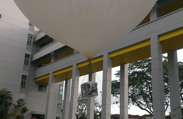
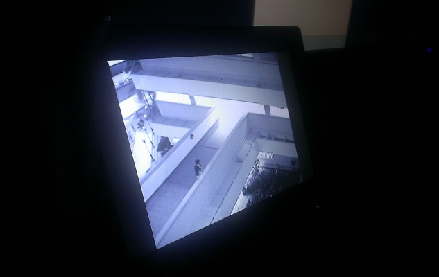
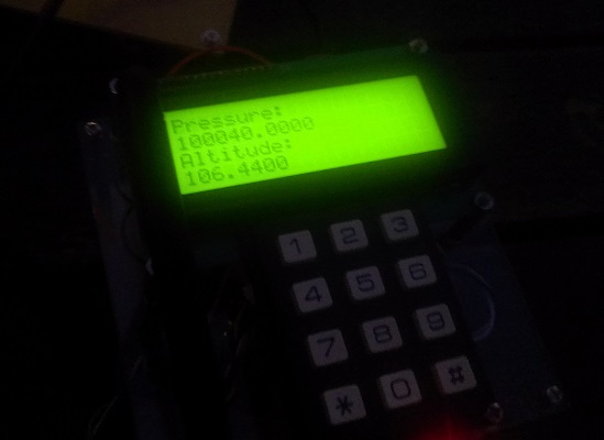
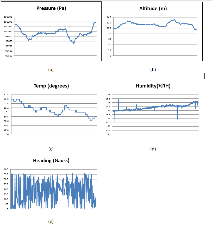
| Requirement |
Testing Results |
| Mass | 1035 grams |
| Dimensions (LxBxH) | 13 x 19 x 13 |
| Operating Height | not able to determine as maximum altitude possible was 30m due to windy conditions |
| Orientation and Heading | able to determine |
| Sensors | temperature, pressure, altitude, humidity, heading |
| Camera Control | can be manipulated from ground |
| Communication Link | established between satellite and ground |
